PCB Materials Glossary 
FR4
FR stands for Fire Retardant. FR4 is a glass fiber epoxy laminate. It is the most commonly used PCB material. A 1.60mm FR4 uses 8 layers of (7628) glass fiber material. The red UL/manufacturers logo is in the middle (layer 4). There are two types of logos: red and blue logos. Red is UL94-V0, blue is UL94-HB. If you have a blue logo material, it is either XPC (phenolic) or G10 (glass epoxy); these are older materials. The main usage of G10 nowadays is for thin watch circuit - since it is very punchable. In 1.50/1.60mm FR4 the logo is in the middle layer (layer 4) of the common 8 layer construction.
Standard rigid FR4
Designed for use in high density multi-layer boards, FR4 is suitable for surface mount multi-layers, MCM-Ls, direct chip attach, automotive and wireless communications. The characteristics of FR4 also make it particularly beneficial in high volume fine line multi-layers and PCMCIA applications.
The predictability and consistency of this material provides for tremendous ease of processing at the circuit board fabrication site, and its electrical and mechanical characteristics make it user friendly for both designers and fabricators of critical circuits.
The predictability and consistency of this material provides for tremendous ease of processing at the circuit board fabrication site, and its electrical and mechanical characteristics make it user friendly for both designers and fabricators of critical circuits.
CEM-3
(CEM - Composite Epoxy Material)
(CEM - Composite Epoxy Material)
CEM-3 is very similar to FR4. Instead of woven glass fabric a 'flies' type is used. CEM-3 has a milky white color and is very smooth. It is a complete replacement for FR4 and has a very large market share in Japan.
Prepreg
A 'prepreg' is an epoxy coated glass fabric. It has two usages: as a dielectric in multilayer PCBs, and as the raw material for FR4. 8 layers of '7628' prepregs are used in one sheet of 1.60mm FR4. The central layer (number 4) usually carries the red company/UL logo.
Prepregs come in various thicknesses:
Prepregs come in various thicknesses:
Type
Weight [g/m²]
Thickness [mm]
Warp/Weft
106
25
0.050
22 x 22
1080
49
0.065
24 x 18.5
2112
70
0.090
16 x 15
2113
83
0.100
24 x 23
2125
88
0.100
16 x 15
2116
108
0.115
24 x 23
7628
200
0.190
17 x 12
PCB materials for Flex and Rigid-flex applications
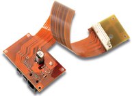
Flex and Rigid-flex circuit boards have become increasing popular due to their unique applications. Flex and Rigid-flex circuit boards can do what regular standard rigid circuit boards can not do. They can fold, twist, and wrap around tight/small packaging area.
Most flex circuit boards are being manufactured using "Kapton", a material developed by Dupont Corporation. This polyimide film based material is resistant to heat, has dimensional stability and a low dielectric constant of 3.6. There are three variants of the Kapton material:
Most flex circuit boards are being manufactured using "Kapton", a material developed by Dupont Corporation. This polyimide film based material is resistant to heat, has dimensional stability and a low dielectric constant of 3.6. There are three variants of the Kapton material:
- Pyralux LF (Acrylic Base Adhesive-not Flame Retardant)
- Pyralux FR (Acrylic Base Adhesive-Flame Retardant)
- Pyralux AP (Adhesiveless-for more Demanding high-performance applications)
PCB materials for RF / Microwave / High Speed applications
As circuit speeds continue to escalate and wireless communications proliferate, the need for a high frequency circuit boards becomes paramount. Here are some typical materials used in high frequency PCB constructions:
Rogers Corporation
Arlon
Park-Nelco
Getek
Rogers Corporation
- 5870/5880 series
- 3003/3006/3010 series
- 6002/6006 series
- 4003/4350 series
- TMM4/TMM6/TMM10
Arlon
- DiClad and CuClad series
Park-Nelco
- N4000 series/ N5000 series/ N6000 series/ N7000 series/ N8000 series
Getek
- Loss tangent = .012 (slightly high) (usage in analog circuits up to 1.2 ghz and up to 2.0ghz in digital applications) (Stability in temperature variations good)
- Er = 3.5 to 4.3 (at 1.0mhz) (specific Er is dependent on glass-resin- ratio - Er is virtually constant form 1.0mhz to 2.0ghz)
- CTEr = +220ppm per degrees C (high). Tg is 180 degrees C.
- Electro-deposited Copper only. (helps in peel strength and de-lamination but somewhat limits etch width tolerance due to undercutting).
Hybrid PCB materials
Hybrid circuit boards are a way of reducing cost. It is a process of combining standard FR4 laminate with other RF/microwave/high speed laminate. The technology gives engineer the ability of controlling the design on desired layer(s) yet still reducing cost with standard FR4 on the remaining portion of the circuit boards. Learn more about the PCB materials at:
Browse Our Range


