Board Outlines
You need to provide the correct board outline on one of the gerber files (we prefer it be on soldermask layer). The outline needs to be constructed by single line (not multiple line segments) that connect to each other (10 mil line width preferred), and the dimensions are calculated using the center of the line. See examples below:
An example of a good Outline
(Notice how the measurement is taken from center of the line)
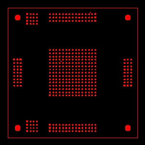
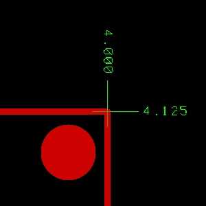
Some examples of bad outlines:
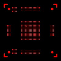
Crop marks instead of line
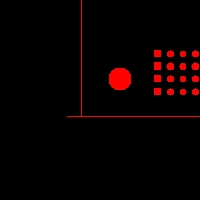
Not Clean at the corner
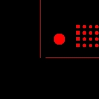
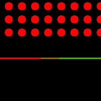
Here the outline is made using multiple lines and overlapping lines, instead of a single line. This is not allowed.
An example of a good Outline
(Notice how the measurement is taken from center of the line)


Some examples of bad outlines:

Crop marks instead of line

Not Clean at the corner


Here the outline is made using multiple lines and overlapping lines, instead of a single line. This is not allowed.
Filled Areas
Filled areas must be filled using 10 mil outlines with 1 mil overlap. Use 0 and/or 90 degree lines to do the fill. We have found that some CAD systems will leave gaps on the fill areas when using 45 degree line. Crosshatch is not allowed. See examples below.
Here we have one mil (0.001") overlap
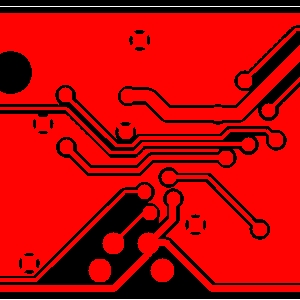

This is an example of a plane area using a Cross Hatch pattern. Cross Hatch patterns are not allowed.
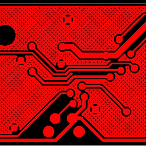
Here we have one mil (0.001") overlap


This is an example of a plane area using a Cross Hatch pattern. Cross Hatch patterns are not allowed.
